I’m working in really cool project with some of my students. We want to make a magic hoodie. The idea is simple: We take a basic hoodie, some LEDs, a color sensor, and an Arduino board. We decorate the hoodie with the LEDs, and try to make them mimic the color detected with the sensor. But the TCS3200 sensor is trickier than I first thought, so in order to understand it better, I’ve written this post. Hope it’s useful.
The sensor
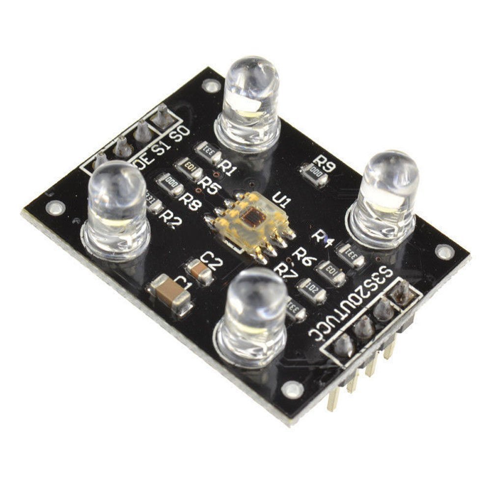
The TCS3200 is a color sensor that comes with 4 white LEDs. It has an array of photodetectors with different filters (red, green, blue, clear). Inside the chip there’s an oscillator which produces a square-wave output whose frequency is proportional to the intensity of the chosen color.
Specs
- Single-Supply Operation (2.7V to 5.5V)
- High-Resolution Conversion of Light Intensity to Frequency
- Programmable Color and Full-Scale Output Frequency
- Power Down Feature
- Communicates Directly to Microcontroller
- S0~S1: Output frequency scaling selection inputs
- S2~S3: Photodiode type selection inputs
- OUT Pin: Output frequency
- OE Pin: Output frequency enable pin (active low), can be impending when using
- Support LED lamp light supplement control
- Size: 28.4x28.4mm
Filters and frequencies
The TCS3200 allows the microcontroller to activate the different filters and also lets it scale the output frequency (fo). For this purpose, the S0, S1, S2 and S3 pins are used. The microcontroller can set the pins to HIGH or LOW in order to obtain the desired results.
To control de output frequency:
| S0 | S1 | OUTPUT FREQUENCY SCALING |
|---|---|---|
| L | L | Power down |
| L | H | 2% |
| H | L | 20% |
| H | H | 100% |
To control the color filters:
| S2 | S3 | PHOTODIODE TYPE |
|---|---|---|
| L | L | RED |
| L | H | BLUE |
| H | L | Clear |
| H | H | GREEN |
At this point I had some doubts:
- What’s the order of the frequency?
- What’s the output frequency proportion?
- What’s the proportion between different colors?
Figuring out how it works
Time to look at the datasheet!
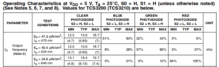
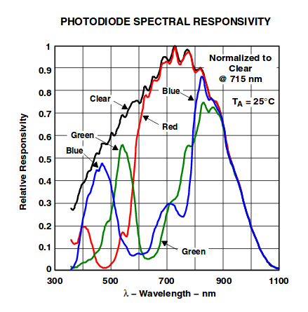
Ok, here I can see the frequency values that I can expect when exposing the sensor to different colors. By looking at this information I can start thinking about a proper algorithm to measure color. I need to generate 8-bit RGB values that I can use to set the colors of the LED strip. I could measure the frequency with the clear filter first and then with the rest in order to generate this values consistently, as it seems that the frequency obtained with the color filters are dependent on the one obtained with the clear one.
Yes, I can break down the steps now:
- Measure the four frequencies.
- Compute the percentage of the clear frequency obtained by each color.
- Transform (I’ll start by mapping), the percentages obtained to a 8-bit scale
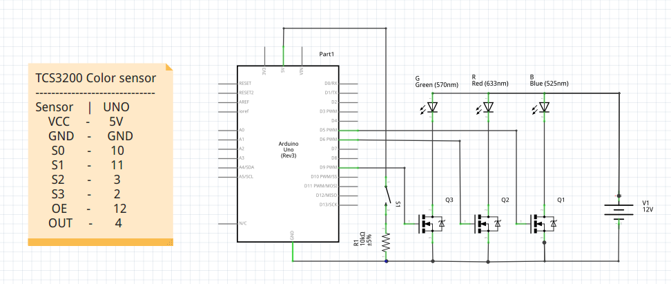
- Set the colors to the LED strip. (I’ve used a setup similar to this one).
I feel like writing a small library for this, It will ease everything.
Testing
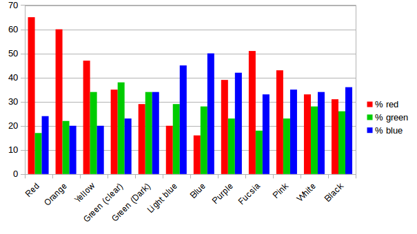
It turned out that reading the datasheet and trying to decide the color from it just wasn’t enough. I needed to take some samples and watch the output for myself, so I wrote a very simple code (using my newly created library) that gave me the measured frequency for each filter as an output (the average of ten samples) and then tested it with different colors. These were the results:
![]()
With this data I was able to write a second iteration of my code, in particular, a generateRGB function which was able to translate the input provided by the sensor into 8-bit RGB values that I could use for the led strip. I used the graphs shown above to discuss with my students how could we approach this problem and they were very surprised of the results of their guessing. They had engineered a solution, and it worked!
The solution consisted on looking at the dominant color and then guessing the possible color “family” depending on the other values, in order to correctly mp the inputs to the outputs. In the following code, the array values contains the “clear frequency”, the % of red, % of green and % of blue. By % of [color] I mean the frequency obtained with that color filter expressed as a percentage of the clear one. The rgb array is an array containing the resulting 8-bit values: red, green and blue.
void Hoodie::generateRGB(int rgb[3], unsigned long values[4]) {
  // Begin with red. If >40 means it's the dominant color
  if (values[1] > 40) {
    // Red, Orange, yellow, Fucsia, pink...
    // Check blue
    if (values[3] > 30 ) {
      //Mix of red and blue: Fucsia / Pink
      rgb[0] = 255; // Max value
      rgb[1] = map(values[2], 18, 23, 0, 100); // For pink
      rgb[2] = 100;
    } else {
      // Mix of red and green: Yellow - Orange - Red
      rgb[0] = 255;
      rgb[1] = map(values[2], 17, 34, 0, 255); //min: red, max: yellow
      rgb[2] = 0; // We don't want any blue
    }
  // If not, check Blue
  } else if (values[3] > 40) {
    //check red
    if (values[1] < 30) {
      // No red: Blue colors / Turquoise
      rgb[0] = 0; // No red
      rgb[1] = map(values[2], 23, 30, 0, 100);
      rgb[2] = map(values[3], 40, 50, 0, 100) ;
    } else {
      // No green: Purple colors
      rgb[0] = map(values[1], 16, 39, 0, 100);
      rgb[1] = 0; // No green
      rgb[2] = 255;
    }
  // If not, check green
  } else if (values[2] > 30) {
    //check red
    if (values[1] < 30) {
      //Mix of green and blue
      rgb[0] = 0; // No red
      rgb[1] = 255;
      rgb[2] = map(values[3], 23, 34, 0, 100);
    } else {
      //Mix of green and red
      rgb[0] = map(values[1], 27, 34, 0, 100);
      rgb[1] = 255;
      rgb[2] = 0; // No blue
    }
  } else {
    // White / black
    if ( values[0] > 70000) {
      rgb[0] = 255;
      rgb[1] = 255;
      rgb[2] = 255;
    } else if (values[0] < 15000) {
      rgb[0] = 0;
      rgb[1] = 0;
      rgb[2] = 0;
    }
  }
}
Yes, it could be better, but it solves the problem for this project. The next step will be putting the pieces together in the hoodie and perform tests in different conditions :D